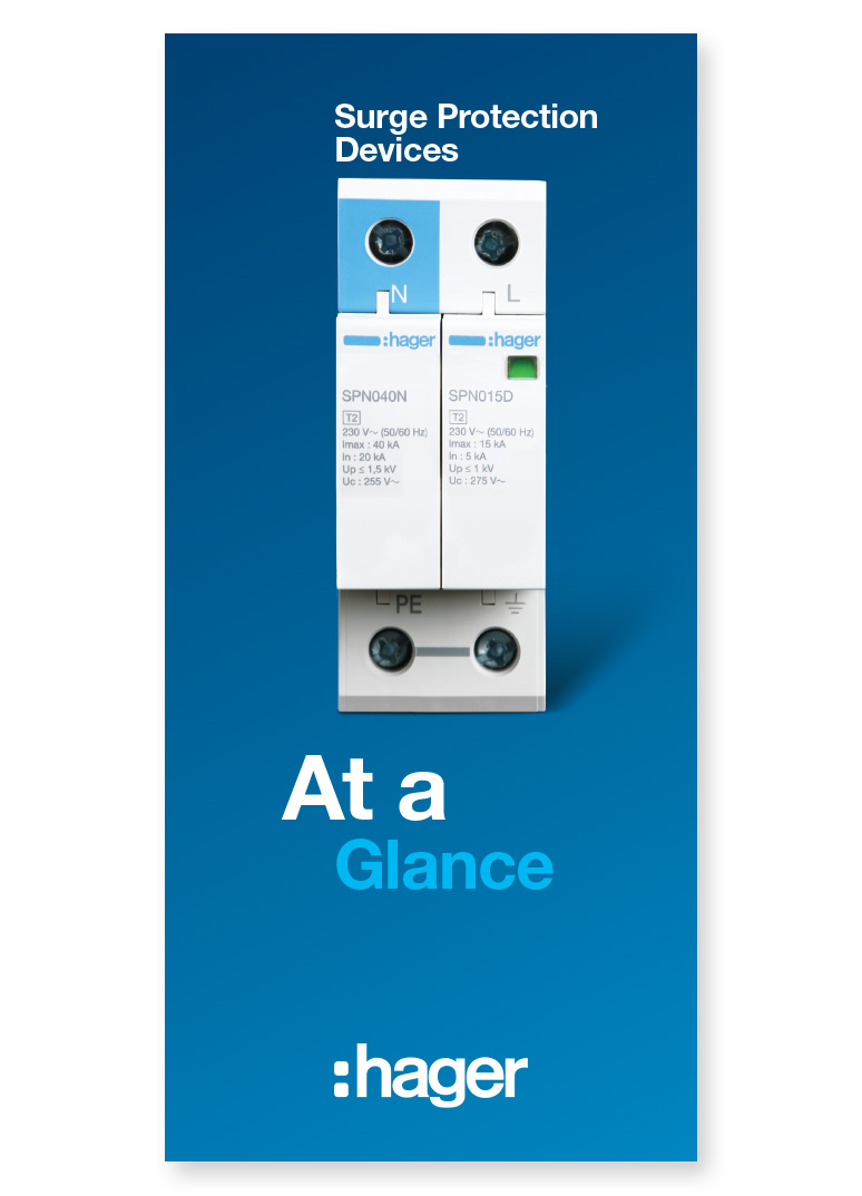


Surge Protection
The whole nature of how electrical equipment is used in homes and at work has evolved; with everyday activities relying on electronic equipment.
Products such as computers, printers, flat screen televisions, industrial control equipment such as PLC’s, alarms, microwaves and washing machines are common place. These can all be vulnerable to transient overvoltages, which can significantly reduce the equipment’s lifespan through degradation and damage.
A transient overvoltage or surge is a short duration increase in voltage measured between two or more conductors. In short this means anything from microseconds (millionths of a second) to a few milliseconds (thousandths of a second) in duration.
Surge Protection Devices (SPD's)
 SPD’s protect electrical and electronic equipment against transients, originating from lightning, switching of transformers, lighting and motors.
 These transients can cause premature ageing of equipment, downtime, or complete destruction of electronic components and materials.
Selection Criteria
Surge protection devices are classified according to their functions:
Type 1
SPD which can discharge partial lightning current with a typical waveform 10/350 μs. Usually employs spark gap technology.This, if required, will be installed in the primary distribution board at the origin of the electrical installation. A Type 1 SPD does not in itself offer the required protection level and must be used in conjunction with coordinated type 2 devices. An installation with a lightning protection system will require a Type 1 SPD.
Type 2
SPD which can prevent the spread of overvoltages in the electrical installations and protects equipment connected to it. It usually employs metal oxide varistor (MOV) technology and is characterised by an 8/20 μs current wave.This device would normally be in sub-distribution boards and in the primary distribution board if there was no requirement for a type 1 device
Type 3
These SPDs have a low discharge capacity. They must therefore only be installed as a supplement to Type 2 SPD and in the vicinity of sensitive loads. Type 3 SPD’s are characterised by a combination of voltage waves (1.2/50 μs) and current waves (8/20 μs).
Terminology
Iimp – Impulse current of 10/350 μs waveform associated with Type 1 SPD’s
In – Surge current of 8/20 μs waveform associated with Type 2 SPD’s
Up - The residual voltage that is measured across the terminal of the SPD when In is applied
Uc - The maximum voltage which may be continuously applied to the SPD without it conducting.
In – Surge current of 8/20 μs waveform associated with Type 2 SPD’s
Up - The residual voltage that is measured across the terminal of the SPD when In is applied
Uc - The maximum voltage which may be continuously applied to the SPD without it conducting.
Maintenance
Most SPDs have an indication window that they are operational. If the indicator is green they are providing protection. If they are red then they have reached ‘end of life’ and will need replacing. Often there is a replaceable cartridge which can simply be withdrawn and replaced with a new operational device.